Fuel Farm Electrical Design, Supply & Commissioning


Fuel Farm Electrical Design, Supply & Commissioning
As a part of a large joint venture project in the Hunter Valley, a new diesel and lubricant fuel farm has been constructed for the Mine Infrastructure Area. PCE was engaged by the principal contractor to complete the electrical and control system design, through to system commissioning. Post design, PCE was also awarded the supply contract for the associated 415V Motor Control Centre (MCC) and motor Visual Break Isolators.
Electrical & Control System Design
As the project electrical and control system designers, PCE was responsible for the following aspects of the fuel farm package:
- Detailed electrical & instrumentation design inc. equipment selection
- Design & specification of Motor Control Centre
- Power system modelling, load flow, short circuit & arc flash studies
- Protection design
- Safety in Design / Design Risk Assessment / RAMBO
- Earthing & lightning protection
- Functional safety – SIL 2 system as per AS61508
- PLC Functional specification – Detailed fuel farm operating philosophy
- PLC programming – Allen Bradley ControlLogix
- HMI programming – Allen Bradley Panelview
- Soft Starter programming – Allen Bradley PowerFlex
- Factory Acceptance Testing (FAT)
- Detailed installation scope of work inc. cable schedule and bill of material
- Site Acceptance Testing (SAT) / System commissioning
Supply of Motor Control Centre & Factory Acceptance Testing
In collaboration with our subcontract partner, PCE was responsible for the manufacture, factory acceptance testing and delivery of the fuel farm’s Motor Control Centre and motor Visual Break Isolators.
A key challenge for this project was designing and manufacturing an MCC that was compliant to the current Australian Standards for switchboards (AS/NZS 61439), whilst meeting the client’s requirement for IP rating, form factor and installation conditions. The result for the client was a modular switchboard, compliant to AS/NZS 61439 that was housed in an IP66 outer shell fabricated to the client’s specification.
Prior to delivery to site, PCE completed the configuration of the MCC control system, including PLC, soft starters, HMIs, network switches and incomer power meter. To facilitate testing of the control system, the field control panels (supplied by others) were transported to the MCC testing facility. Temporary wiring between the MCC and control panels was used to replicate the site installation, allowing fuel farm sequencing to be verified and witnessed by the client.
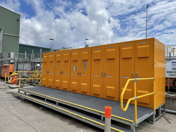
Figure 1 - Installed Motor Control Centre (MCC)
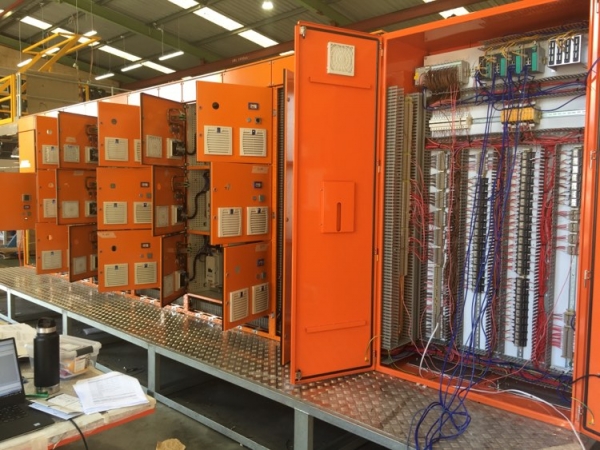
Figure 2 - MCC Undergoing Factory Acceptance Testing (FAT)

Figure 3 - Installed Visual Break Isolators (VBI)
Site Acceptance Testing
Working closely with our client and principal contractor, PCE completed site acceptance testing of the fuel farm electrical and control systems. In accordance with the client’s site standards, SAT was split across several phases:
- C0 Pre energization checks – including construction walkdown, risk assessments, IO bridging register, commissioning barricading, isolation lockouts & notice of energization;
- C1 Control system checks – including PLC communication, instrument calibration, functional safety verification & PLC IO testing;
- C2 Direction testing – motor bump tests;
- C3 Load testing – commissioning of the fuel farm functionality with diesel and lubricants transferred, operated up to rated capacity; and
- C4 Electrical & control system handover – Removal of IO bridging, walkdown with client, demonstration of control system with site operations personnel.
A key challenge of the commissioning phase of this project was juggling the ongoing construction of the fuel farm, whilst progressing commissioning safely. To ensure that the project was completed on time, PCE’s site acceptance testing was split across functional units of the control system, i.e., diesel delivery, diesel dispensing, and the various lubricant systems. As a result, PCE was able to successfully commission several diesel & lubricant systems whilst construction of other systems was finalised.
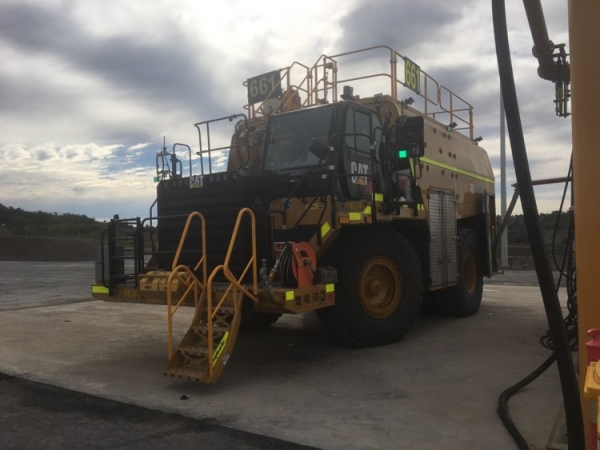
Figure 4 - Mobile Plant on Refuelling Hardstand
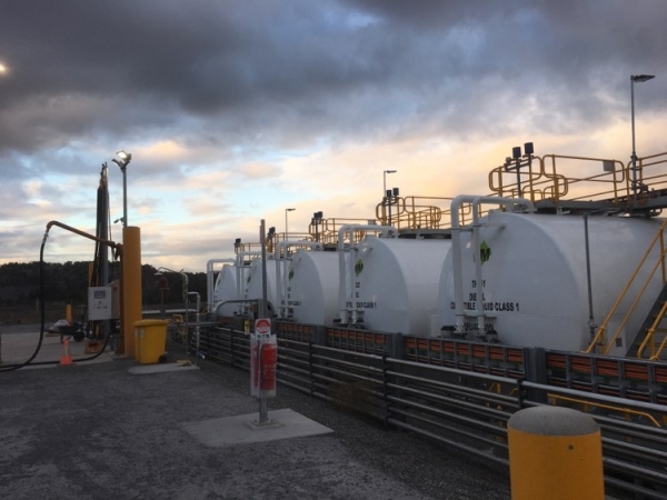
Figure 5 - Diesel Storage Tanks
Looking Forward
PCE is proud to have supported our client through the design, construction, and commissioning of this diesel & lubricants fuel farm. Post-handover, we continue to support the operation across a range of design, earthing & functional safety works, and look forward to furthering this relationship into the future.