
132/11 kV Switchyard Expansion Design


50 MVA, 132/11kV Switchyard Expansion Design
Summary:
PCE was engaged to complete the electrical design for a 50MVA switchyard expansion at a large copper mine in central New South Wales. Working closely with the principal contractor, PCE completed detailed 132kV switchyard and 11kV substation designs including associated power studies. The detailed electrical design included SLD’s, Schematics & Termination Diagrams, Equipment Selection, CT Sizing, 132/11kV Transformer Protection Design, Protection Coordination, Arc Flash, Load Flow, Earthing, Lightning, PFC and Harmonics studies, Bill of Materials, Cable Schedule, HV Isolation Procedures & standards audits (AS3000 and AS2067).
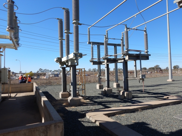
Figure 1 - 132kV Switchyard Tie-In Point
About the Project:
The Switchyard consisted of 132KV ABB 2500A GW56 double-break disconnector / earth switch, Siemens 3150A circuit-breaker, surge arrestor, Ampcontrol 132/11kV 50MVA transformer, 6.6kV 25A Neutral Earthing Resistor, 11k/415V 200kVA Auxiliary transformer and PFCU.
The 11kV Switchboard has 1 incomer and 8 feeders. Each incomer and feeder is protected by an ABB REF615 IED (Intelligent Electrical Device) for 50, 51 59 68 protective functions. The transformer has an ABB RET620 IED for 26Q, 49W, 50, 51, 63V, 68, 71Q, and 90V protective functions.

Figure 2 - 11kV Switchroom During FAT
The PFCU was designed for 12MVAR correction in 6 steps (1-1-2-2-3-3) based on a power factor correction study completed using PTW. This enables capacitor banks to switch in 1MVAR increments up to 12MVAR. Capacitor banks require time to discharge prior to re-energization and the step combination minimises switch-in delay, using the standby capacitor bank. Each capacitor bank has an ABB REV615 for 50, 51, 55TD, 67N, 27, 59 protective functions. A separate ABB RVT6 power factor controller controls switching of the steps based on demand.

Figure 3 - 12MVAR PFCU & 11kV Switchroom In-Situ
The 50MVA main and 200kVA auxiliary transformers (by Ampcontrol) were designed to comply with AS60076. The transformer protective devices such as oil level switch, transformer winding RTD etc. are connected to the corresponding ABB IED for monitoring and tripping.
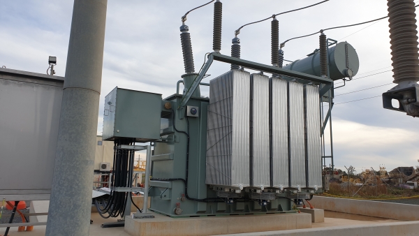
Figure 4 - New 50MVA 132/11kV Transformer
Detailed Design Considerations:
Each piece of electrical equipment was selected based on operating conditions:
Circuit breakers are selected based on rated current (A), insulation voltage (kV), impulse withstand voltage (kV), breaking time (ms), rated short time withstand current (kA) and peak withstand current (kA).
Disconnectors and Earth switches are selected on operating voltage (kV), rated current (A), rated short-circuit withstand current and duration (kA & seconds) and Impulse withstand voltage (kV).
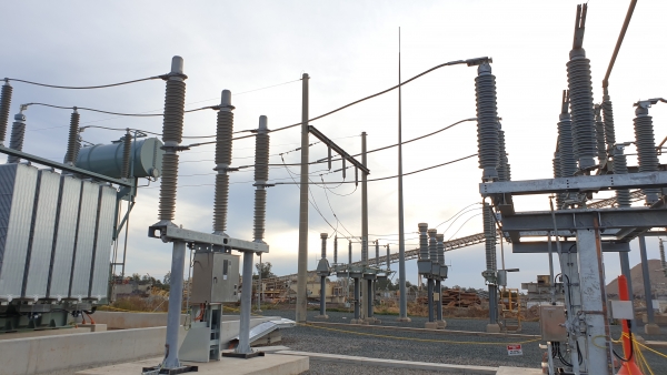
Figure 5 - New 132kV Switchgear
Transformers are selected based on installation condition, MVA rating, HV & LV side voltages, vector group, Insulation rating (kV), Impedance (Z%), Insulation medium (Oil, Gas, Dry) etc.
It is also important to check High Voltage (HV) clearances when installing equipment and structures such as minimum phase-to-earth, phase-to-phase, non-flashover, and ground safety clearances according to AS2067.
The Switchroom control and protection system was designed to operate using a 160AHr, dual 110VDC Battery Charger. The battery charger was selected based on maximum demand, and considering inrush current of undervoltage, shunt trip and other relay coils.

Figure 6 – 132/11kV Transformer Protection Mimic Panel
Current transformers (CT) are chosen based on the application. i.e. Protection and Metering.
A protection current transformer must only saturate at sufficiently high levels to allow an accurate measurement of the fault current by the protection; whose operating threshold can be very high. Therefore, protection CT’s are expected to have an Accuracy Limit Factor (ALF) that is very high.
A metering current transformer requires good accuracy around the nominal current value. The metering instruments do not need to withstand currents as high as the protection relays. Hence, the metering CTs, unlike the protection CTs, have the lowest possible Safety Factor (SF) to protect these instruments through earlier saturation.
Other design inputs, such as design review and risk assessment, contributed to the rigour of our design. We ensured that a detailed design review was carried out and all relevant parties were available for the session – client, and principal contractor. Safety in design was facilitated by a third party with PCE contributing to the review.
Power Studies (Fault level / Load flow / Protection Coordination / Arc Flash / PFC & Harmonics) are essential for a complex electrical reticulation design. Fault level analysis is essential for equipment selection and determining the clearing times of the overcurrent devices. Load flow analysis helps predict equipment loading, tap changer positions and voltage variations at all the buses. Protection and coordination using Time-Current Characteristic (TCC) curves and analysis is needed to provide necessary protection and to avoid false trips, relay mis-operation, and mis-coordination. An Arc Flash analysis is required to determine the incident energy available at specific electrical equipment that an operator would be exposed to during operation. Hence appropriate PPE can be implemented.
Earthing Studies were completed including; effects of modification of the earth grid in the 132kV yard to accommodate the new 50MVA transformer; connection of new equipment in the 132kV yard including transformer, switchgear, disconnector, and associated structures to the earth grid; extension of the existing earth grid to accommodate connection of the new 11kV switchroom, PFC equipment and aux. transformer; modelling of the extended earth grid using Groundmat software; and calculating the new Earth Potential Rise (EPR) in the event of a 132kV earth fault. All of which was assessed to ensure compliance with the latest earthing requirements for mining operations as specified in AS2067:2016.
A Lightning Protection risk assessment was also conducted in accordance with AS1768:2007 and recommendations provided based on the results of the assessment.